
Scottie
Jetboaters Captain
- Messages
- 451
- Reaction score
- 566
- Points
- 212
- Location
- Helena, Alabama
- Boat Make
- Yamaha
- Year
- 2013
- Boat Model
- X
- Boat Length
- 21
I wanted a way to monitor the temperature of each engine on my boat (2013 212x, 1.8l HO engines). In stock form, you will get an overheat warning in the multi-function display (tach) when there is a problem, but you will get no warning before that, and you will get no actual temperature reading. I wanted more than that, as my lake can be a bit weedy sometimes. So I decided to install temperature senders in the cooling outlet lines (aka "the pissers"), and accompanying gauges in the dash. There's more than one way to skin the cat here, but I'll detail the method I chose. The most difficult part of this install may be figuring out where to install gauges if your dash is stock. There are also temperature senders with external digital gauges available, which would also work. So take this write-up as more of a general direction with some important specifics, rather than a "you must do it this way", as your specific situation will very likely be different. On to the details.
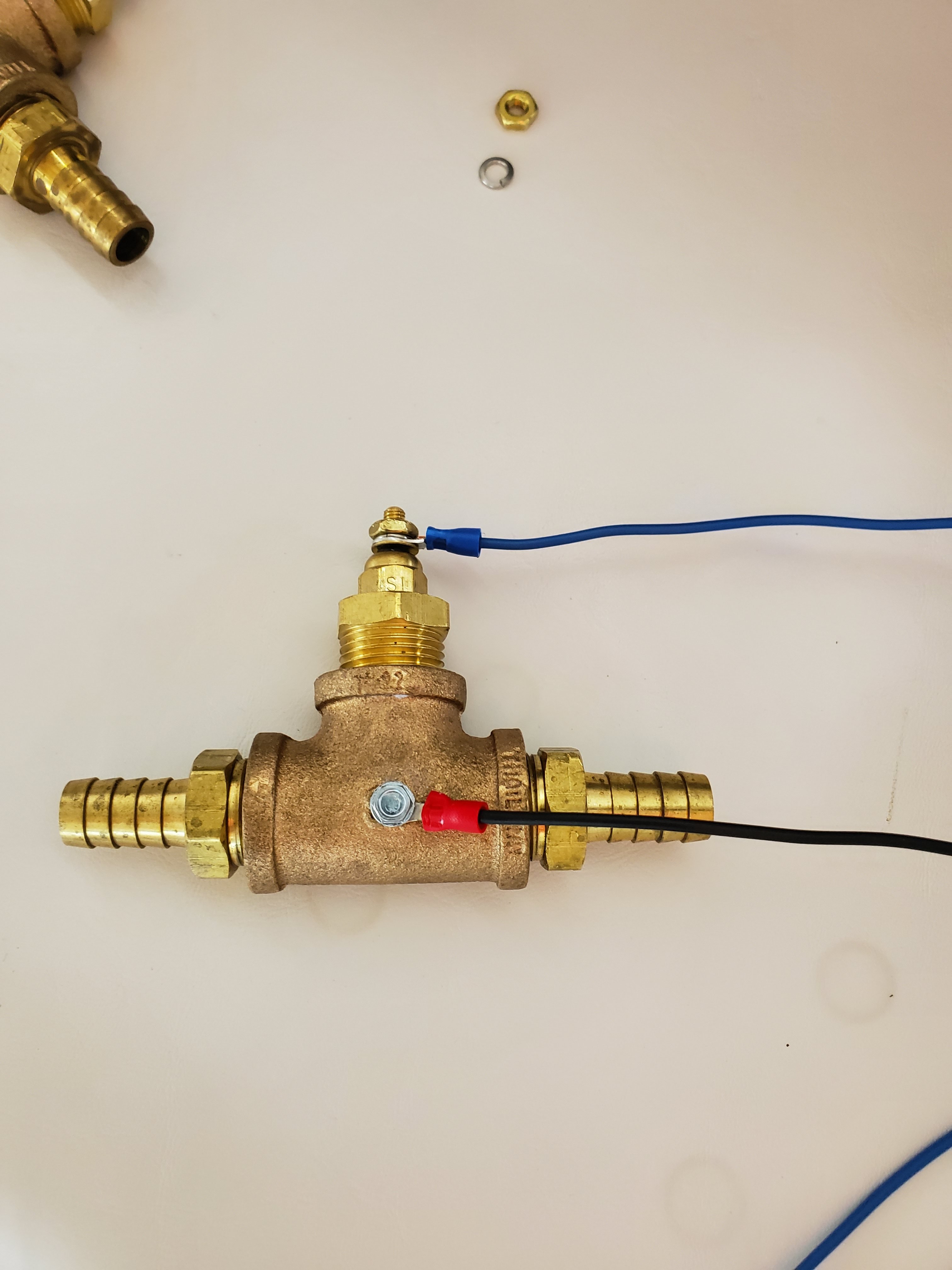
In my boat (and I believe many, if not all others) the outlet lines are 1/2" hose. Most temperature senders are 1/8" NPT. So the overall goal is to get a T fitting that can be installed into the hose when cut, which has a female 1/8" NPT fitting for temp sender installation. There's a lot of ways you could accomplish this. There are even "ready-made" units like this one Amazon Link that might be very simple, especially if you're planning to use an external display. I did not find one for 1/2" hose, but I bet it exists, or you could reduce it down to make it work. I had brass fittings laying around, so this is the method I chose. This also opens up your temperature sender options, to include those which require an "engine block ground", as you can ground the brass fittings by simply adding a ground wire. This "T" could also be constructed with plastic, for probably much cheaper, but if you go that route, you'll need a temperature sender with a ground wire attached already. The parts listed below are for one engine only. Simply double it for twin engines.
Parts list:
1x Brass Tee, 1/2" NPT female: Amazon Link
2x Brass hose fitting adapter, 1/2" barb x 1/2" NPT male: Amazon Link
1x Brass 1/2" NPT Male to 1/8" NPT female reducing bushing: Amazon Link
1x 2" temperature gauge: The first one I purchased is here Amazon Link. This one looked good, and worked, but did not read lower than 100 degrees, so it looked broken most of the time. The second one I purchased (the one in the pics) is here. Amazon Link. The second one reads 68-302F and INCLUDES a temp sender, that also has an exposed ground wire, so a plastic "T" fitting could be used.
1x Temperature sender (MUST match the gauge): The first one I purchased is here. Amazon Link. The second one was included with the second gauge, here. Amazon Link
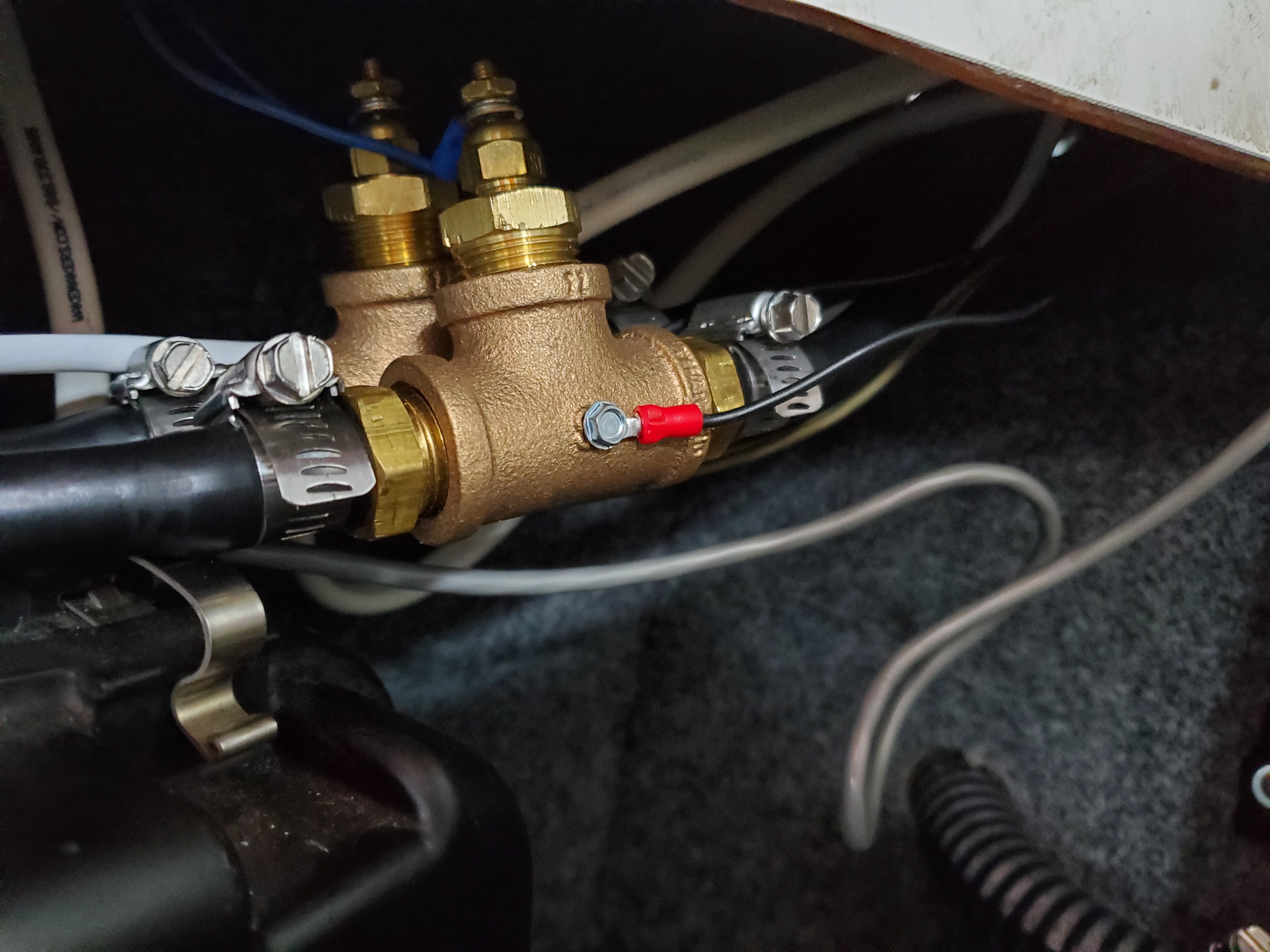
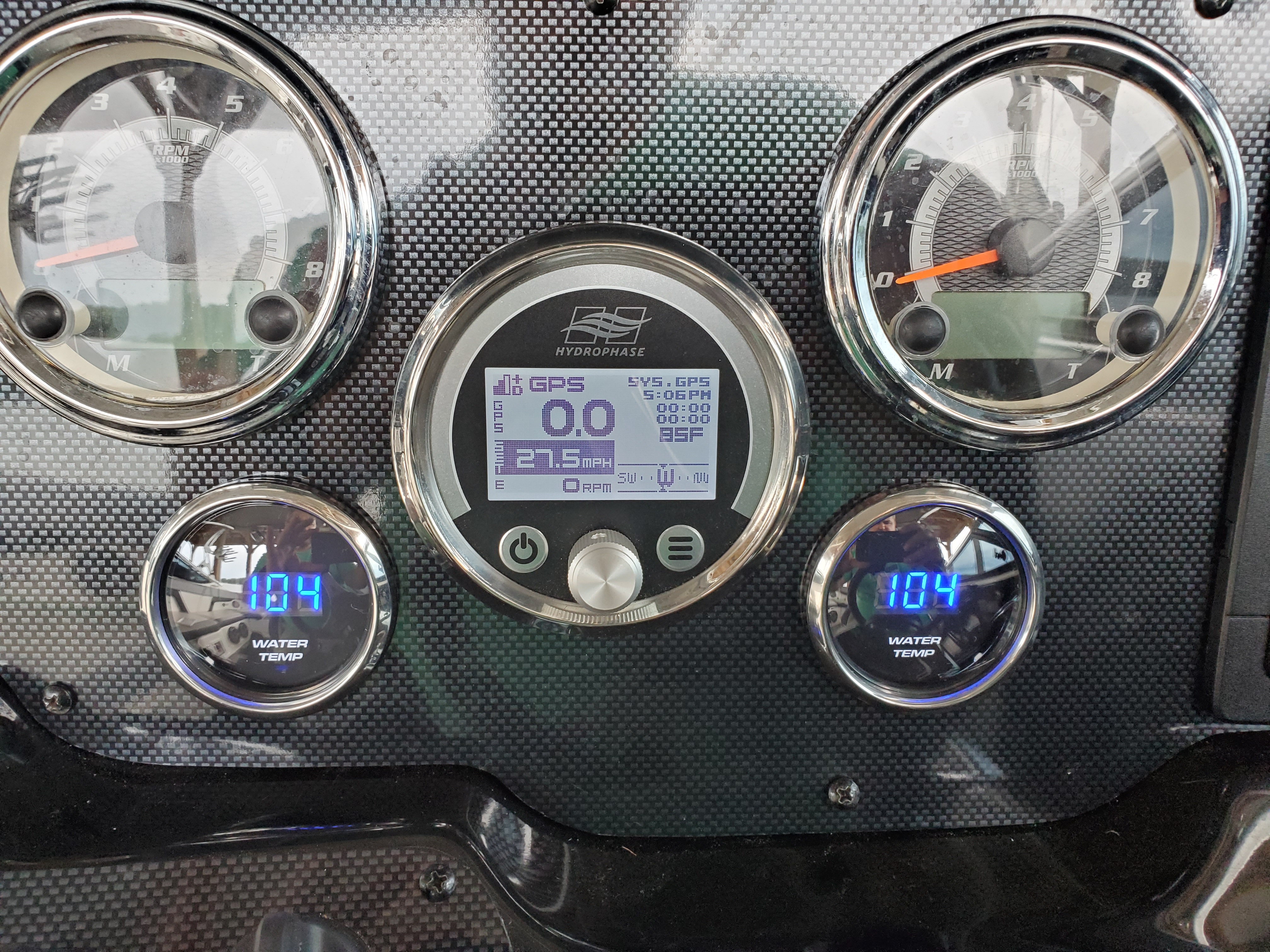
Once you have the correct parts, installation is very straightforward. Assemble the "T" as in the pics below. Cut your coolant outlet hose, and insert the "T". I cut the hoses between the engine output and the "pisser" fittings. My hoses were easily accessible just under the forward lip of the engine hatch, before the hoses pass into the starboard side storage compartment, just above the air filter box. Connect a ground wire to your brass "T" if required, and run a sender wire from the temp sender up to the dash. The gauge you purchase will have a wiring diagram that you should follow, but its basically +12V, -12V, and the wire from the sender. There will also be a +12V for whatever light the gauge has, and nicer gauges will have a "dimming" connection which you can wire to the output of your nav light, so that when you turn your nav light on, the gauge lights will either change from on to off, or dim from bright to less bright, depending on your gauge. There are 3 pics below. One of the completed "T", one of the installed "T", and one of the installed gauges. Hopefully, this is enough info for you to complete your version of this project if you decided to do so, but I'm happy to answer any additional questions if I can.
In my boat (and I believe many, if not all others) the outlet lines are 1/2" hose. Most temperature senders are 1/8" NPT. So the overall goal is to get a T fitting that can be installed into the hose when cut, which has a female 1/8" NPT fitting for temp sender installation. There's a lot of ways you could accomplish this. There are even "ready-made" units like this one Amazon Link that might be very simple, especially if you're planning to use an external display. I did not find one for 1/2" hose, but I bet it exists, or you could reduce it down to make it work. I had brass fittings laying around, so this is the method I chose. This also opens up your temperature sender options, to include those which require an "engine block ground", as you can ground the brass fittings by simply adding a ground wire. This "T" could also be constructed with plastic, for probably much cheaper, but if you go that route, you'll need a temperature sender with a ground wire attached already. The parts listed below are for one engine only. Simply double it for twin engines.
Parts list:
1x Brass Tee, 1/2" NPT female: Amazon Link
2x Brass hose fitting adapter, 1/2" barb x 1/2" NPT male: Amazon Link
1x Brass 1/2" NPT Male to 1/8" NPT female reducing bushing: Amazon Link
1x 2" temperature gauge: The first one I purchased is here Amazon Link. This one looked good, and worked, but did not read lower than 100 degrees, so it looked broken most of the time. The second one I purchased (the one in the pics) is here. Amazon Link. The second one reads 68-302F and INCLUDES a temp sender, that also has an exposed ground wire, so a plastic "T" fitting could be used.
1x Temperature sender (MUST match the gauge): The first one I purchased is here. Amazon Link. The second one was included with the second gauge, here. Amazon Link
Once you have the correct parts, installation is very straightforward. Assemble the "T" as in the pics below. Cut your coolant outlet hose, and insert the "T". I cut the hoses between the engine output and the "pisser" fittings. My hoses were easily accessible just under the forward lip of the engine hatch, before the hoses pass into the starboard side storage compartment, just above the air filter box. Connect a ground wire to your brass "T" if required, and run a sender wire from the temp sender up to the dash. The gauge you purchase will have a wiring diagram that you should follow, but its basically +12V, -12V, and the wire from the sender. There will also be a +12V for whatever light the gauge has, and nicer gauges will have a "dimming" connection which you can wire to the output of your nav light, so that when you turn your nav light on, the gauge lights will either change from on to off, or dim from bright to less bright, depending on your gauge. There are 3 pics below. One of the completed "T", one of the installed "T", and one of the installed gauges. Hopefully, this is enough info for you to complete your version of this project if you decided to do so, but I'm happy to answer any additional questions if I can.


